I'm working on a science project and there's one aspect of home wiring I need to find out (don't worry, I'm not messing with wiring - this is all on paper). Since 120V outlets in a home can be wired to either of the two 120V legs that come in from the power company, would it be a true statement that outlets on different breakers could be out of phase with each other? In other words if Bedroom 1 is tied to leg 1 and bedroom 2 is tied to leg 2 is it reasonable to assume that the sine waves measured from outlets in bedroom 1 will be out of phase with the sine waves measured from outlets in bedroom 2?
Asked
Active
Viewed 1.3k times
11
-
1You may also like to know more about reactance. Reactance is where the current and voltage become out of phase, and in industrial applications with nonlinear loads this creates harmonic currents on the neutral. – Kris Jun 08 '15 at 16:05
-
1This is probably one of the most commonly misunderstood concepts in American residential power. Most electricians even get it wrong. – David Pfeffer Jun 10 '15 at 13:35
6 Answers
13
Sort of. It depends on your frame of reference.
If you're looking at the ungrounded (hot) conductor from each receptacle, you'll end up with a 240 volt circuit. Since it's a single circuit, it can't be out of phase with itself. If you hooked up an oscilloscope to the ungrounded (hot) conductor of each receptacle, you'd get a single 240 volt sine wave.
If you're looking at the two separate circuits (e.g. the ungrounded (hot) and grounded (neutral) conductor from each receptacle), then you'll end up with two 120 volt circuits 180° phase shifted from each other. If you hooked up the oscilloscope to the ungrounded (hot) conductor and grounded (neutral) conductors from each receptacle (4 leads instead of 2), you'd see two 120 volt sine waves 180° phase shifted from each other.
The two sine waves should look something like this.
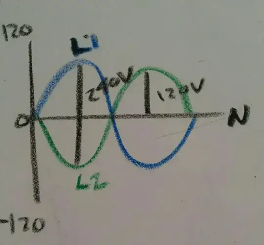
Because the waves are phase shifted 180°, the electrical potential between the legs (at the peak) will be 240 volts. While the potential between either line and "neutral", will be 120 volts.
If the waves were not phase shifted, they'd be at the same potential (or have 0 volts between them).
So while this is not a multi phase system, it's also not a simple single phase system. Technically it's known as a "Single split phase system".
All of this; of course, assumes that the ungrounded (hot) conductors are from different legs of the service.
Tester101
- 131,561
- 78
- 320
- 610
-
Yes I'm looking at two separate circuits so it makes sense that they are out of phase. Thanks for the clarity. – Michael Baker Jun 08 '15 at 17:18
-
I'm sorry, but this is incorrect. @RobotAndy has the right answer. To explain with an example, if they were 180 degrees out of phase, then connecting across the two phases would yield 0V, not 240V. – David Pfeffer Jun 10 '15 at 13:34
-
8@DavidPfeffer Go hook up an oscilloscope. It's a single phase, with a center tapped "neutral". If you measure line to line, you'll see a 240 volt sine wave. If you measure line (L1) to "neutral" (N), you'll see a 120 volt sine wave. If you measure line (L2) to "neutral" (N), you'll also see a 120 volt sine wave. However, the two 120V waves will be shifted 180° from each other. So while one wave is peaking at +120V, the other will be peaking at -120V. I agree that "phase" might not be the best word, but the idea is the same. – Tester101 Jun 10 '15 at 13:48
-
@Davis Sorry the OP is asking about the sinusoidal wave relationship between a transformer. The voltage is irrelevant. – Kris Jun 10 '15 at 14:13
-
@DavidPfeffer I've added a bit more detail, to help you understand what I'm saying. – Tester101 Jun 10 '15 at 19:19
-
1
-
As I pointed out down below to Henry: They are only 180° out of phase if you first measure one from Neutral to Hot and then measure the other from Neutral to Hot since you are measuring them both in different directions. You are reversing the polarity. There is actually no phase displacement. If you measured L1 to neutral and then neutral to L2 you would see no polarity reversal. That is really what you are talking about. Not a phase shift. – ArchonOSX Apr 06 '16 at 23:54
-
Another interesting concept is algebraically your first drawing would add up to zero whereas your second drawing would add up to 240. It would seem that two phases 180° out would add up since there is 240 volts between peaks but vectorially two vectors 180° out would cancel to zero. All this is moot though since there is only one phase and the two legs of a center tapped transformer are simply one half of the whole. They are in phase with each other when measured in the same direction. – ArchonOSX Apr 07 '16 at 00:06
-
3BTW its a bit misleading to show a scope graph with the y axis going to 120v since if you did that on a 120v RMS system (all household power in the US) the y axis peak would be ~172v. Handheld RMS meters would only ever show you 120 or 240, but that's a different way of measuring. If you want to show 120v on your scope graph you should shade the whole area under the waveform, since that's what mathematically equals 120v. – Jeff Meden Apr 07 '16 at 16:06
-
4@JeffMeden I agree, but I'm trying (and failing) to explain a concept. The numbers on the graph are meaningless, and are only included to make it more familiar to the general audience. If I wanted to be overly technical in my answer, I wouldn't have drawn the diagrams in crayon. – Tester101 Apr 07 '16 at 16:10
-
2@ArchonOSX: Why would you "add up to zero"? Voltage is a difference. – GManNickG Apr 07 '16 at 19:24
-
How can you split up one sine wave with 240 amplitude to two 120V sine waves such that they're "out of phase" - i get that it's the one voltage line, but what I don't get is how you got two 120V lines from it – azizj Feb 19 '17 at 19:47
-
@AzizJaved because the neutral is a center tap, so half the coil is on each side of it. – Tester101 Feb 19 '17 at 22:38
5
This is mainly a semantic question.
From an electrician's point of view, US household supply is a single 240V that can be split into two center-tapped hot legs.
From a mathematical or E&M point of view, the different legs have voltages that are 180º out of phase, and therefore I think it would be safe to call them two phases once they're separated.
(Left to the reader as an excercise: if you take a brick and cut it in half, do you have one brick or two bricks?)
Hank
- 14,093
- 10
- 44
- 47
-
1I agree. We seem to be getting hung up on the meaning of the word "phase". It seems to me all the answers are saying the same (or similar) things, yet somehow some are being down voted while others are up voted. – Tester101 Jun 11 '15 at 01:19
-
1They are only 180° out of phase if you first measure one from Neutral to Hot and then measure the other from Neutral to Hot since you are measuring them both in different directions. There is actually no phase displacement. Hence the term single phase. – ArchonOSX Apr 06 '16 at 22:47
-
1Can we just use the Wikipedia definition? "Phase difference is the difference, expressed in degrees or time, between two waves having the same frequency and referenced to the same point in time" if you measure each source of a residential center tap aka "split phase" to ground, the peak of 172v will be 180 degrees apart, plain and simple. – Jeff Meden Apr 07 '16 at 15:58
-
1If you take a brick and cut it in half, you will have a single split brick. Hence, single split phase. – Substantial Jan 30 '17 at 23:47
1
In a typical residential North American 120VAC, the answer is NO
The reason is your house only receives one phase, and thus that one phase cannot be out-of-phase with itself. Changing your frame of reference (by measuring voltage from the N rather than across L1 and L2) does suddenly not make them out of phase.
If your real question is: "Will the voltage measured from N to L1 always be shifted 180 degrees compared to the voltage measured from N to L2?" then the answer to that is "Yes"
...however that fact alone is not enough for it to be considered a separate phase of power.
If you truly had two phases, then the voltage difference between them would vary and occasionally be 0.
RobotAndy
- 343
- 1
- 2
- 6
-
Sorry the OP is asking about the sinusoidal wave relationship between a transformer. The voltage is irrelevant. While one sinusoidal is 360° the split-phase terminology describes the relationship of the neutral at the 180° center point. The neutral has zero potential voltage because of the sinusoidal wave canceling out the other. – Kris Jun 10 '15 at 14:13
-
OP asks two things: "would it be a true statement that outlets on different breakers could be out of phase with each other" - the answer to which depends on how accurately you're defining "phase" and "is it reasonable to assume that the sine waves measured from outlets in bedroom 1 will be out of phase with the sine waves measured from outlets in bedroom 2" – RobotAndy Jun 10 '15 at 15:47
-
a single sinusoidal wave that is tapped in the center is technically out of phase by 180°. This is a true statement. – Kris Jun 10 '15 at 15:55
-
1Again, the voltage-waveforms may appear out of phase. I think that is covered in my statement of "Will the voltage measured from..." (which I will correct since it doesn't read well atm). – RobotAndy Jun 10 '15 at 16:10
-
3So frustrating I don't have enough credibility here to comment on the actual post, but the problem with the pictures posted by Tester101 on the other post is that there isn't a GREEN and BLUE line. There is only one line! If you truly had a green and blue line, you would at some point be able to measure 0V between them with your test equipment - but you can't! You will always have 240V difference between them, that's the subtle difference between split phase and real 180 degree two phase. – RobotAndy Jun 11 '15 at 01:41
-
1@RobotAndy If you use @ before a users name, the system will notify them directly. – Tester101 Jun 11 '15 at 15:51
-
5@RobotAndy I'm confused by your last comment. You do understand that when you hook up a volt meter, you're actually measuring RMS voltage right? In my drawing, the BLUE line represents the voltage over time as measured between L1 and N, while the GREEN line represents the voltage over time as measured between L2 and N. I could have drawn an additional RED line, that could show the voltage over time measured between L1 and L2. In which case you'd see a sine wave with an amplitude of 240 volts. The period of my diagram is 1/60th of a second. – Tester101 Jun 11 '15 at 15:59
0
Voltages across each leg will be 180 deg out of phase....remember that voltage is a DIFFERENCE so if voltage across leg 1 to neutral (V1) is positive the other will measured negative (-V2) (out of phase by 180) relative to V1. (The numbers V1 and V2 are both positive numbers). Recall that voltage is a DIFFERENCE between two points. So we have V1- (-V2) which is 240 volts if both V1 and V2 are 120 volts. A Minus times a minus number is a positive number so V1-(-V2) = V1 + V2.
Richard MS physics, BSEE
0
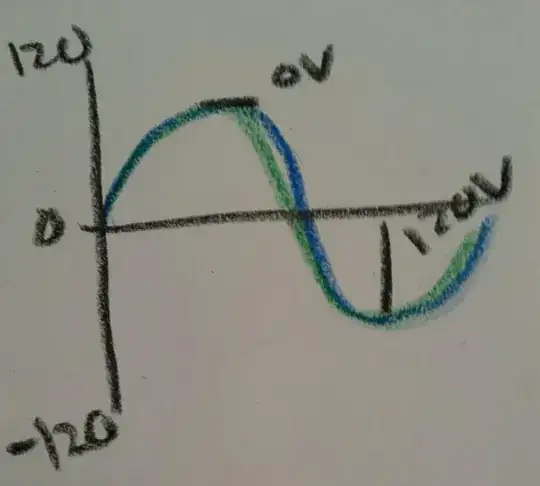
Yes. Technically they're 180 degrees out of phase if the transformer is 120/240 split phase. The neutral is tapped at the center of the coil and each side of the neutral is wound 180 out of phase from the other. A 120/208Y transformer would have each phase 120 degrees out of phase.
Edit: Here is a recent diagram I made to help illustrate the concept.
Kris
- 4,837
- 2
- 12
- 32
-
I'm sorry, but this is incorrect. @RobotAndy has the right answer. To explain with an example, if they were 180 degrees out of phase, then connecting across the two phases would yield 0V, not 240V. – David Pfeffer Jun 10 '15 at 13:34
-
2You are mistaken. Please delete or update your comment as it is misleading. – Kris Jun 10 '15 at 23:34
0
Using vector sums,
If we assume that V1 + V2 = VT
Where
V1 is from the center tap of the transformer to one phase (L1)
V2 is from the center tap of the transformer to the other phase (L2)
and L1 = 120 V at an angle of zero degrees
and L2 = 120 V at an angle of 180 degrees
and VT = the voltage sum of V1 and V2 (i.e., voltage across both phases)
Using Kirchoff's voltage law (i.e., going around the circuit)
VT = V1 + V2' = V1 + (-V2)
VT = (120, angle zero degrees) - (120, angle -180 degrees)
VT = (120, angle zero degrees) + (120, angle zero degrees)
VT = 240, angle zero degrees
The above math supports that the L1 and L2 are 180 degrees out of phase
JCS
- 1
-
You are presupposing that the phases are out of phase, so the subsequent math is only proving the presupposition- which is more precisely the underlying question (are the outlets (or legs, or bus bars in the panel) simply out of phase in a residential electrical system?). Now, if you had simply stated that 240V is measured (and calculated) by the difference between two voltage potentials, and that 120V minus negative 120V equals 240V, then the relevance of using measured voltage as proof that the phases were equal and opposite, could have been meaningful (but redundant per Tester101's answer). – Ben Welborn Apr 06 '16 at 19:57