3

I'm trying to figure out what might be wrong with some exterior GFCI receptacles that I have.

The problem is that this is an old house, and I'm not really sure what is happening between the receptacles and the breakers. Since the receptacles are all outside, the wiring to these receptacles runs underground, and I have no idea what junctions (or lack thereof) have been made.

I'm using a Commercial Electric GFCI outlet tester, like this one:

https://images.homedepot-static.com/productImages/cc6d7656-65fd-4f30-b66c-226d62c6f1fe/svn/multimeters-ce-hgt6120-64_1000.jpg


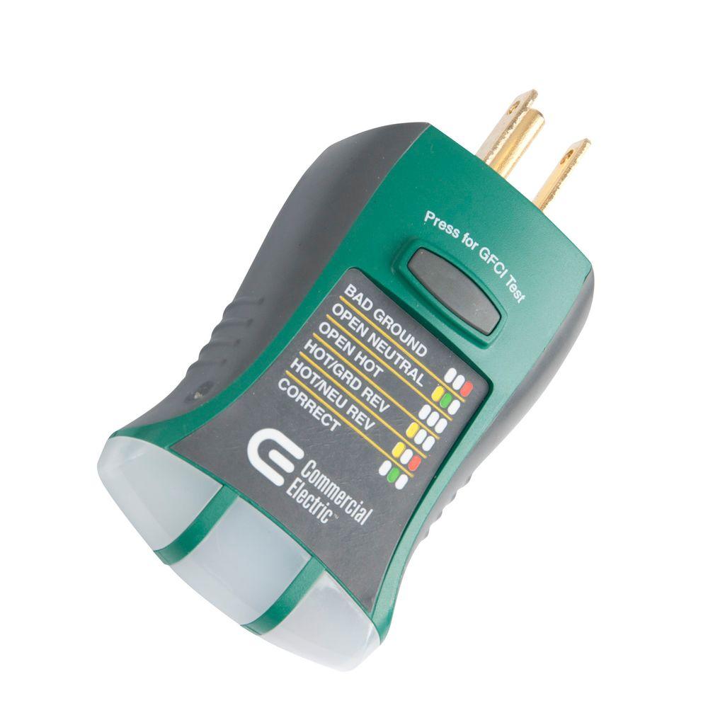
I've got four GFCI receptacles connected to two breakers. Of these four, two are one model, and two are another model (I'm mentioning this in case different models of GFCI receptacles might have different behaviors).

On circuit breaker 1:

GFCI receptacle 1, model 1: lights up | OFF | OFF | RED | indicating BAD GROUND. Pressing the GFCI button successfully trips the GFCI and the lights then switch to | OFF | GREEN | OFF | indicating CORRECT (this doesn't make sense to me).

GFCI receptacle 2, model 2: lights up | OFF | GREEN | OFF | indicating CORRECT. Pressing the GFCI button successfully trips the GFCI and the lights then switch to | OFF | OFF | OFF | indicating OPEN HOT (or no power?).

On circuit breaker 2:

GFCI receptacle 3, model 1: lights up | OFF | GREEN | OFF | indicating CORRECT. Pressing the GFCI button successfully trips the GFCI and the lights then switch to | OFF | OFF | OFF | indicating OPEN HOT (or no power?).

GFCI receptacle 4, model 2: lights up | OFF | OFF | RED | indicating BAD GROUND. Pressing the GFCI button has NO EFFECT.


My analysis:

  1. I think GFCI receptacles 2 and 3 are fine and are behaving as a properly wired, properly grounded GFCI receptacle should behave with a GFCI outlet tester.

  2. I think GFCI receptacle 4 is behaving as a properly wired, but not properly grounded GFCI receptacle should behave with a GFCI outlet tester. As this receptacle is very near GFCI receptacle 3 which seems to be properly grounded, I'm thinking to just run an external ground wire from receptacle 3 to receptacle 4 and everything should be all set.

  3. What the hell is going on with GFCI receptacle 1? At first it seems like it is just another ground that isn't actually grounded, like GFCI receptacle 4. But why the hell does it change to | OFF | GREEN | OFF | indicating CORRECT wiring when the GFCI breaker trips? That makes no sense.

Daniel
  • 211
  • 1
  • 4
  • 7

3 Answers3

5

Normally, the legends on a 3-light tester are useless and wrong, so I call them "magic 8-ball testers". However, they are simple affairs, with the 3 neon lights connected triangle style across the 3 prongs, and a thinker can get useful info out of that.

Not in your case. That tester has a microcontroller stuck in front of the lights. The controller is interpreting the raw signals to "help you out". Just like the old legends, the interpreted answers are wrong. So it destroyed the one thing that made a 3-lamp tester useful: raw data. Into the trash it goes.

Get an old style one, with yellow yellow red lights and Y Y - being a normal reading.

Of course get one with a GFCI tester; that function has nothing to do with the presence or absence of the very unhelpful microcomputer.


I agree with your analysis on receptacles 2, 3 and 4. GFCI #1, ??? Whatever. It is normal for outdoor GFCIs to fail far too soon, that's what you get for leaving them outside. Occam's razor: bad GFCI.


Do you know how GFCIs work? "I spend $20 a socket replacing every receptacle with one of these and the home inspector signs off" is not how GFCIs work.

GFCI is a filtering/safety system that rides between the hot and neutral. It comes in combo w/breaker, standalone (deadfront) or combo w/receptacle. Obviously, the first two don't have any sockets and their one thing is to protect the downline part of the circuit. They can protect the whole circuit - one device.

Here's the thing: the common GFCI receptacle can do that too. That's the one purpose of the LOAD terminals.

So when I hear about GFCIs getting chewed up outdoors, and when I hear about 2 GFCIs on the same circuit, I say it's a good time to figure how the circuit is wired, and find an indoor location to fit one GFCI that'll protect the whole outdoor part of the circuit.

Harper - Reinstate Monica
  • 300,628
  • 26
  • 286
  • 734
  • 1
    You can also use a GFCI breaker when you cannot figure out the best location for the GFCI receptacle to be located. – ratchet freak Nov 27 '18 at 13:07
  • Sorry about that. My take (from what I've seen, but you've seen plenty more than I have) is that the microcontroller is in there to handle "interpreting" more stuff, including GFCI. If the GFCI is simply a "short to ground" to get the GFCI to trip then of course that would be fine. I suspect the average user may not know how to easily tell what is "simple" vs. "microcontroller". – manassehkatz-Moving 2 Codidact Nov 27 '18 at 16:49
  • 2
    @manassehkatz yes, they wouldn't know, until they learn how to use the 3 lights for direct reading, then they'd know they have a duff one. Having a computer controlled diagnostic is not the offensive part; rather it's that they made a conscious choice to poach the "design language" of a 3-lamp tester, i.e. Made their computer diagnostic look indistinguishable from a 3-light tester, as if to fool. If it had been made as a narrow stick with 4 lights, I'd be simpatico. – Harper - Reinstate Monica Nov 27 '18 at 16:52
  • 2
    But any computerized tester would still be wrong more than it's right. Wiring problems don't fall into convenient boxes the legend or computer knows about. You get every darn thing. If anything they are made to detect wiring mistakes (at build time), and are simply not optimized to detect wiring failures. – Harper - Reinstate Monica Nov 27 '18 at 17:47
  • I got another tester: https://images.homedepot-static.com/productImages/b1d0dbb3-533b-488c-b176-e0ae4e1e2a4d/svn/commercial-electric-specialty-meters-ms102h-64_1000.jpg – Daniel Nov 30 '18 at 23:14
  • So this, presumably old-style, tester gave me 'OFF | YELLOW | YELLOW' which is 'CORRECT' for GFCI receptacles 1, 2 and 3. The GFCI test button also worked correctly on all three receptacles. GFCI receptacle 4 still shows as 'OFF | YELLOW | OFF' which is 'OPEN GROUND' and the GFCI test button has no effect. So according to this tester, it seems all 4 receptacles are fine, except that receptacle 4 lacks ground, but is still working as intended. I wonder why the microcontroller in the first tester had a problem with receptacle 1. – Daniel Nov 30 '18 at 23:19
  • I took a multimeter to receptacle 1, just to be sure, and I got 123.4V across hot to neutral, 120.4V across hot to ground, and 0V across neutral to ground. – Daniel Nov 30 '18 at 23:20
  • @Daniel yes, that all rings out correct, with outlet 4 not having a ground. Of course that is not the final word on the subject; the microprocessor may be looking at something we don't know it can look at. I am a little troubled by the 0V N-G; try putting a big 1500w heater or hair dryer in the other socket and meausure again, see if the voltage N-G increases. It may increase only by 0.2 volts, which is fine. If it is always the same, you probably have a bootlegged ground. Better to have no ground. – Harper - Reinstate Monica Dec 01 '18 at 00:01
  • I never got to your hair dryer test but I think it was indeed a bootleg ground and the microprocessor-controlled tester was actually smarter than you gave it credit for. I tested the receptacles again, using both testers just for fun, and noticed a small detail I had missed before: on receptacle 1, the microprocessor would actually flash | OFF | GREEN | OFF | (CORRECT) for a split second before changing to | OFF | OFF | RED | (BAD GROUND). – Daniel Dec 04 '18 at 01:01
  • I ran a ground wire from receptacle 2 (known good) to receptacle 1 and now the microprocessor tests it as | OFF | GREEN | OFF | (CORRECT) just like receptacles 2 and 3. So I'm thinking there was a ground, good enough for the trip function on both testers to work, but only the microprocessor was able to tell that it wasn't a good ground. The split second green was like "oh there's a ground, but wait a minute..." I'm still not sure about the microprocessor behavior to show | OFF | GREEN | OFF | (CORRECT) after tripping the GFCI, but it was right about the bad ground, it seems. – Daniel Dec 04 '18 at 01:06
  • Perhaps the results are less reliable with an edge case like a flaky ground, but you have to hand it to the microprocessor as I wouldn't have thought there was any problem at all if I had just used the simple tester from the beginning. That odd test result made me take a second look at the situation. – Daniel Dec 04 '18 at 01:08
0

You really have 2 problems. The first is your tester. The 2nd is the 1 GFCI that won't trip. Since the tester showed a bad ground there is no way for the test function on the GFCI to work. Adding a ground to that circuit should fix the problem if it looks like there is a ground it may be a bootleg ground (tapped from the neutral). From the information provided there is nothing wrong with your GFCI devices, but the wiring to 1, possibly 2, is incorrect.

manassehkatz-Moving 2 Codidact
  • 115,769
  • 11
  • 130
  • 326
Ed Beal
  • 102,735
  • 4
  • 75
  • 155
  • That is the normal and expected behavior when using an external GFCI tester on a receptacle with a "No Equipment Ground" sticker on it. The external tester has no path to create a ground fault with. The internal GFCI test button should work. – Harper - Reinstate Monica Nov 27 '18 at 17:54
  • I would agree but the OP did not state that it was labeled just the tester said bad ground. Old house was the comment but even houses in the 60's had 3 wire. – Ed Beal Nov 27 '18 at 18:18
  • I'm not concerned about the GFCI that won't trip because that is standard behavior for a GFCI with a bad ground. I'm concerned about the GFCI that shows bad ground, then DOES trip (which is the opposite of expectation) and then changes to show CORRECT wiring after the GFCI has tripped??? – Daniel Nov 27 '18 at 22:20
  • Daniel the GFCI doesent use the ground in the detection circuit. The circuit measures the hot/ netural balance if it becomes more than 6ma it will trip. The magic 8 ball testers as Harper called them and my belief that the magic 8 ball is more accurate than these testers is the real problem as both our answers suggest. If you examine the schematic for a gfci you will find the connection to ground is made through a high value resistor for the test other than that it is not used or switched. – Ed Beal Nov 27 '18 at 22:58
0

Part of your problem may be: too many GCFI's. All GFCI's in the same area can be chained, saving money trouble and vampire energy. First in the chain protects all the others downstream.

So fix one GFCI, remove all the rest.


It is also legal in the USA under the NEC to have no ground, on two wire circuits. Those outlets should be market "GFCI no Equipment Ground".

Bryce
  • 10,884
  • 17
  • 69
  • 112
  • That only works if the GFCIs are connected line to load, as GFCIs are often installed that way out of obliviousness rather than intent. We often recommend that newbies leave the tape across the load terminals, and attach to line only. That spares them unintended consequences of putting things on GFCI protection that they do not realize they are putitng on GFCI protection. – Harper - Reinstate Monica Nov 27 '18 at 17:58
  • 1
    In some cases multiple GFCI'S are needed. This is the case when the refrigerator is at the end of a branch with 2,3,4 countertop outlets. Each gfci is powered from the line side load side not used at all. With this configuration the fridge won't trip the GFCI so there are times when multiples are needed. – Ed Beal Nov 27 '18 at 18:25